Compliance
Organizer:
- Organized by
-
-
ISO 2768 – [with PDF] General Geometrical Tolerance Standards and Technical Drawings
-
ISO 2768 – [with PDF] General Geometrical Tolerance Standards and Technical Drawings
What is ISO 2768?
ISO 2768 and derivative geometrical tolerance standards ISO 2768–mk and ISO 2768–fh are intended to simplify drawing specifications for mechanical tolerances. ISO 2768 is mainly for parts that are manufactured by way of machining or removal of materials. Variations on dimensions without tolerance values are according to ISO 2768, all tolerance limits are given in mm.
International organizations, governmental and non-governmental, in liaison with ISO, also take part in the work. ISO collaborates closely with the International Electrotechnical Commission (IEC) on all matters of electrotechnical standardization.
General tolerance ISO 2768 does not specify where to use these tolerances. Tolerance class is defined as per design requirements and manufacturing capability. For example : for sheet metal parts ISO 2768–mk is used. And for machined components ISO 2768–fh can be used.
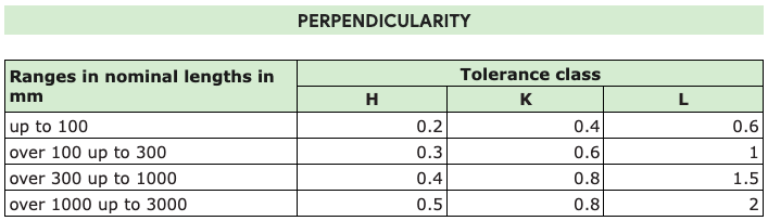
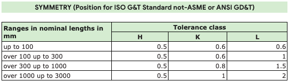
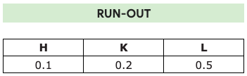
ISO 2768-2 : 1989, General tolerances — Part 2:
Geometrical tolerances for features without individual tolerance indications.
ISO 8015 : 1985
Technical drawings — Fundamental tolerancing principle.
Variations on dimensions without tolerance values are according to ” ISO 2768″. All tolerance limits are given in mm.
ISO 2768 and derivative geometrical tolerance standards are intended to simplify drawing specifications for mechanical tolerances. ISO 2768 is mainly for parts that are manufactured by way of machining or removal of materials.


Draft International Standards adopted by the technical committees are circulated to the member bodies for approval before their acceptance as International Standards by the ISO Council. They are approved in accordance with ISO procedures requiring at least 75% approval by the member bodies voting.
International Standard ISO 2768-1 was prepared by Technical Committee ISO/TC 3, Limits and fits.
This first edition of ISO 2768-1, together with ISO 2768-2 : 1989, cancel and replace ISO 2768 : 1973.
ISO 2768 consists of the following parts, under the general title ‘General tolerances’:
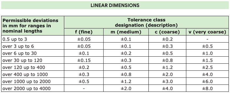
Part 1: Tolerances for linear and angular dimensions without individual tolerance indications
This part is intended to simplify drawing indications and specifies general tolerances in four tolerance classes. It applies to the dimensions of work pieces that are produced by metal removal or are formed from sheet metal. It contains three tables and an informative annex with regard to concepts behind general tolerancing of dimensions.
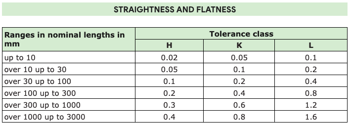
Part 2: Geometrical tolerances for features without individual tolerance indications
This part is intended to simplify drawing indications and specifies general tolerances in three tolerance classes. It mainly applies to features which are produced by removal of material. It contains tour tables and an informative annex A with regard to concepts behind general tolerancing of dimensions, as well as an informative annex B with further information.
Introduction
All features on component parts always have a size and a geometrical shape. For the deviation of size and for the deviations of the geometrical characteristics (form, orientation and location) the function of the part requires limitations which, when exceeded, impair this function.
The tolerancing on the drawing should be completed to ensure that the elements of size and geometry of all features are controlled, i.e. nothing shall be implied or left to judgement in the workshop or in the inspection department.
The use of general tolerances for size and geometry simplifies the task of ensuring that this prerequisite is met.
Scope
This part of ISO 2768 is intended to simplify drawing indications and it specifies general tolerances for linear and angular dimensions without individual tolerance indications in four tolerance classes.
It applies to the dimensions of parts that are produced by metal removal or parts that are formed from sheet metal.
These tolerances may be suitable for use with materials other than metal.
Parallel International Standards exist or are planned, e.g. see ISO 80621) for castings.
This part of ISO 2768 only applies for the following dimensions which do not have an individual tolerance indication:
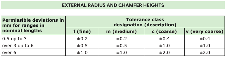
a) linear dimensions:
(e.g. external sizes, internal sizes, step sizes, diameters, radii, distances, external radii and chamfer heights for broken edges);
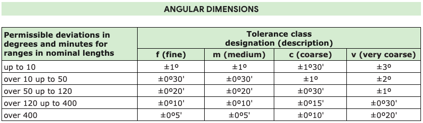
b) angular dimensions:
Including angular dimensions usually not indicated, e.g. right angles (90°), unless reference to ISO 2768-2 is made, or angles of uniform polygons;
c) linear and angular dimensions:
Produced by machining assembled parts.
It does not apply for the following dimensions:
a) linear and angular dimensions which are covered by reference to other standards on general tolerances;
b) auxiliary dimensions indicated in brackets;
c) theoretically exact dimensions indicated in rectangular frames.
The following standards contain provisions which, through reference in this text, constitute provisions of this part of ISO 2768. At the time of publication, the editions indicated were valid. All standards are subject to revision, and parties to agreements based on this part of ISO 2768 are encouraged to investigate the possibility of applying the most recent editions of the standards indicated below. Members of IEC and ISO maintain registers of currently valid International Standards.
Click here to download PDF of ISO 2768 Geometrical Tolerance Standards